Automatic Door Locking with Arduino
Automatic Door Locking and Unlocking System With Arduino.


Components Required:-
1.Arduino MEGA
2.Keypad 4*4
3.Infrared Module (*2)
4.LCD Display 16*2
5.Power Supply(it can be between 5v to 12v max)
(I have used 12v adapter for arduino and a 5v adapter for servo motor)
6.breadboard(optional)
7.box for Fitting the lcd and keypad
8.jumper wires
**(I have used an external power supply for servo motor because, arduino is not capable for supplying large current greater the 600mA and their are two many thing attached to arduino here which is continuously taking current through it, so it may happen that servo motor stop working due reduction in current)
**(This has happened with me,the arduino keep on going reboot again and again)
Working of the lock:-
Password for this is 1234.
First if the door is closed and we enter the password 1234,it will print "Access Granted" on LCD and the door will open using the servo motor,I have connected a Aluminium Wire with the servo motor to the inner door lock. Now after opening the door it will print "Door is OPEN" ,(this happens due to the ir module placed on the top right of the door,after opening it gives a low signal to arduino).
Now if you just shut the door the ir module give a high signal to arduino(Wall Comes in front of it),and then again servo motor function and closes the door.
If someone wants to come out from inside,he just have to place his hand in front of the second ir module,it gives a low signal to arduino and again the servo motor functions,and opens the door.
 |
Servo motor Attached to inner lock |
 |
Second ir Module Attached to Arduino(for Opening door from inside) |

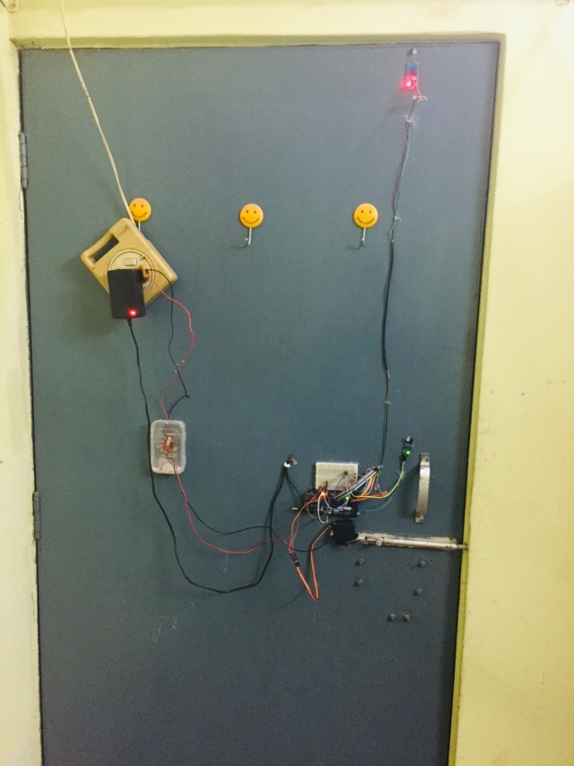 |
Plastic box is the 5v power supply for Servo motor (Arduino is not capable for supplying lagre current greater the 600mA )Arduino Sketch for this lock:--/* This code is writen by Sameer vermaFor More Projects log on to www.arduinoexpert.blogspot.comvideo for the working's --*/// This code is weitten for Educational purposes only#include <Keypad.h>#include<LiquidCrystal.h>#include<EEPROM.h>#include <Servo.h>Servo servo1;LiquidCrystal lcd(22,23,24,25,26,27); // pins of the LCD. (RS, E, D4, D5, D6, D7)char password[4];char pass[4],pass1[4];int i=0;#define ira 28#define irb 29char customKey=0;const byte ROWS = 4; //four rowsconst byte COLS = 4; //four columnschar hexaKeys[ROWS][COLS] = {{'1','2','3','A'},{'4','5','6','B'},{'7','8','9','C'},{'*','0','#','D'}};byte rowPins[ROWS] = {7, 6, 5, 4}; //connect to the row pinouts of the keypadbyte colPins[COLS] = {3, 2, 8, 9}; //connect to the column pinouts of the keypad//initialize an instance of class NewKeypadKeypad customKeypad = Keypad( makeKeymap(hexaKeys), rowPins, colPins, ROWS, COLS);void setup(){Serial.begin(9600);pinMode(11, OUTPUT);pinMode(ira,INPUT);pinMode(irb,INPUT);lcd.begin(16, 2);servo1.attach(10);lcd.setCursor(0,1);lcd.print(" Welcome!!");Serial.print(" Welcome!! ");delay(2000);lcd.clear();lcd.setCursor(0,1);for(int j=0;j<4;j++)EEPROM.write(j, j+49);for(int j=0;j<4;j++)pass[j]=EEPROM.read(j);}void loop(){int vala=digitalRead(ira);int valb=digitalRead(irb);if(vala==HIGH && valb==HIGH){delay(1000);servo1.write(0);check();}else if(vala==LOW && valb==HIGH){lcd.clear();lcd.setCursor(0,0);servo1.write(90);lcd.print("Door is open");Serial.println("Door is open");delay(50);}else if(vala=HIGH && valb==LOW){lcd.clear();lcd.setCursor(0,0);servo1.write(90);lcd.print("Comming out!");Serial.println("Comming Out!");delay(2000);}}void check(){while(i<=4){Serial.println("Enter Password");lcd.setCursor(0,0);lcd.print("Enter Password");if(digitalRead(irb)==LOW){break;}customKey = customKeypad.getKey();if (customKey){password[i++]=customKey;lcd.setCursor(i,1);lcd.print(customKey);Serial.print(customKey);}if(i==4){delay(200);for(int j=0;j<4;j++)pass[j]=EEPROM.read(j);if(!(strncmp(password, pass,4))){lcd.clear();lcd.print("Acess Granted");Serial.println("Acess Granted");servo1.write(90);delay(4000);lcd.clear();i=0;break;}else{digitalWrite(11, HIGH);lcd.clear();lcd.print("Access Denied...");Serial.println("Access Denied...");delay(2000);lcd.clear();lcd.print("Enter Passkey:");Serial.println("Enter Passkey:");i=0;}}}}See the video :-Hope you Enjoyed,reading this tutorial...For any queries , please comment below. |


Nice :D Try to use (CTRL + T) in Arduino IDE when you write code. Your code will looks better ;)
ReplyDeleteOh Yeah, thanks bro ...😲😄😄
Delete